Electronic Circuits - interfacing with a Z80 microprocessor v9 (NTSC analog video signal)
My seb80 custom computer now has its own page here
This is version 9 of my Z80 interfacing project. My goal in this version was to use both input and output devices to generate NTSC analog video signal, which could be displayed on a regular television set.
Previous versions:
Previous versions:
- version 1 - initial wire-up, executes NOPs, observe incrementing address
- version 2 - experiment with and observe machine cycles M2 (memory read) and M3 (memory write)
- version 3 - address and data buses
- version 4 - introduce ROM and run program from it
- version 5 - introduce RAM
- version 6 - oscillator clock, NMI button, and INT/NMI tests
- version 7 - I/O output device
- version 8 - I/O input device
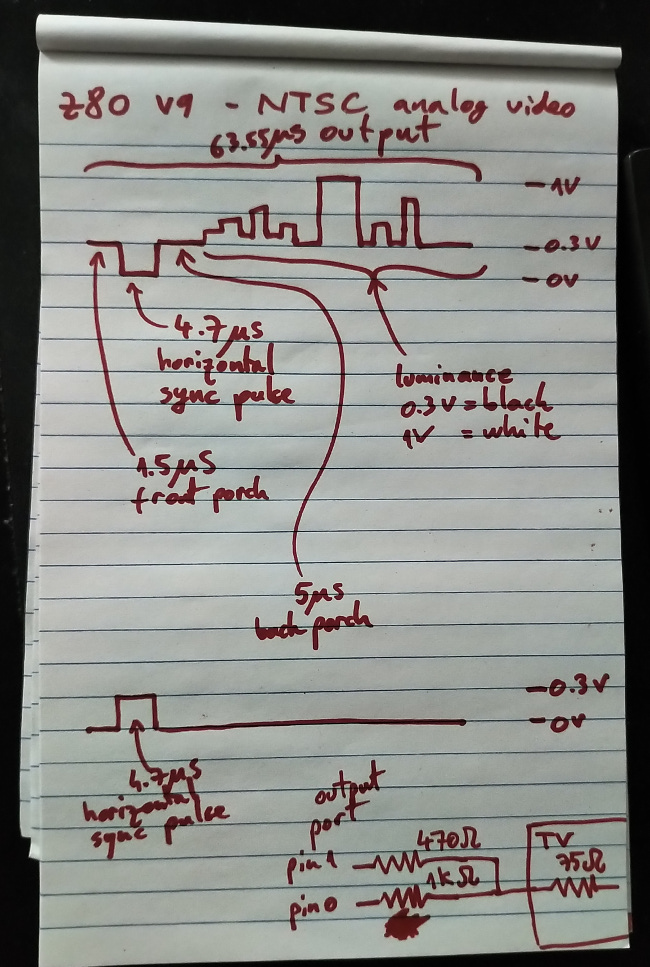
I have restricted the scope of this version to generating luminance-only NTSC signal. This results in grayscale-only output, black to white. Chrominance signal is significantly more difficult to implement, and requires higher clock frequencies than those at which my breadboard prototype computer can operate.
Anything faster than the 3.6864 MHz crystal oscillator I ultimately chose caused system instability.
Generating stable NTSC frames requires consistent timing. Visible scan lines need to have their horizontal sync pulses at the same time, to prevent image distortion (shearing, rolling, etc.) The number of invisible, vertical sync scan lines varies significantly from TV to TV.
The interfacing circuit is very simple. Given that NTSC televisions have a terminating 75 Ohm resistor at their input, it was simple to design a Y resistor network connected to two pins of an output device. Pin 0 had 1k Ohm and pin 1 had 470 Ohm. Approximately, 00b output 0V (sync), 01b output 0.3V (black), 10b output 0.7V (gray), 11b output 1V (white).
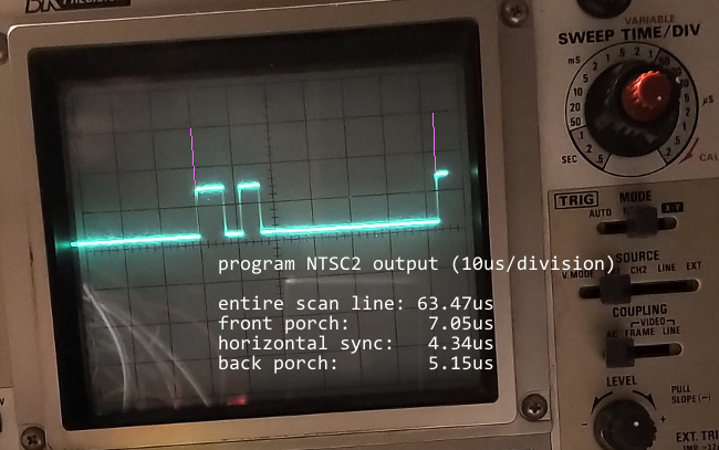
I've used program NTSC2 to get consistent scan line timing, before setting out to display anything on a television set yet.
Programs NTSC4 and NTSC5 below are complete examples of generating static images, as well as dynamic images, based on modifications made by a user via an input.
NTSC4 program - generates a static image
NTSC5 program - generates a vertical bar which can be moved with a button
NTSC4 program listing
;
; program NTSC4
;
; purpose: generate a static NTSC frame
;
; IMPORTANT: all of these timings are specific to a
;            CPU clock frequency of 3.6864 MHz
;
JP start

; data region
colours:
DB 2, 3, 2, 1, 3, 1, 2, 3, 2

start:
LD C, 06h            ; output port
LD A, 1
LD E, 242

OUT (C), A           ; start with front porch level of 0.3V
NOP
NOP
NOP                  ; a small initial front porch

;
; visible scan line loop: generate 242 visible vertical scan lines
;
new_scanline:
; here, output is 0.3V
; here, register E contains remaining visible scan line count
; here, register C contains output port number
; here, register A contains 1
; (since logical 1 outputs 0.3V: front porch level)
                     ; here we're on the front porch

DEC A                ; 4 clocks
                     ; A := 0 (preparing to output 0V for horizontal sync)
OUT (C), A           ; 12 clocks
                     ; falling edge to 0V (logical 0)

                     ; we're now at the start of horizontal sync

INC A                ; 4 clocks, still at 0V
                     ; A := 1, preparing to output 0.3V
OUT (C), A           ; 12 clocks, rising edge to 0.3V (logical 1)
                     ; signal has now risen to the level of the
                     ; back porch

                     ; TOTAL TIME ON HORIZONTAL SYNC
                     ;                   4 + 12 = 16 clocks

                     ; we're at the start of the back porch
                     ; and have risen to 0.3V (logical 1)


; front porch took: 30 clocks
; back porch took: 19 clocks
; horizontal sync took: 16 clocks
; total invisible: 65 clocks
;
; 1 clock = 1 / 3.6864 MHz = 0.271267361us
; total scan line: 63.55us / 0.271267361us = 234.27 clocks per line
;                                            round down to 234
; remaining for visible region: 234 - 65 = 169 clocks
; NOTE: visible region starts on back porch

; IMPORTANT:
;     output voltage is now 0.3V from the back porch
;     available visible region MUST NOT change that output for
;     another 19 clocks

                     ; we're still on back porch

; BEGIN 169 clock area

LD A, R              ; 9 clocks, NOOP instruction

LD HL, colours       ; 16 clocks
                     ; HL := pointer to colour array

OUTI                 ; 16 clocks
                     ; output byte at address in HL to port C
                     ; B := B - 1
                     ; HL := HL + 1
                     ; this changes colour being output and
                     ; advances colour pointer

                     ; NOTE: the back porch can be longer, if
                     ;       available visible area begins
                     ;       with black
                     ;       this 19 clock internval represents
                     ;       the minimum time needed for back porch

                     ; we're now on the available visible region

OUTI                 ; 16 clocks
OUTI                 ; 16 clocks
OUTI                 ; 16 clocks
OUTI                 ; 16 clocks
OUTI                 ; 16 clocks
OUTI                 ; 16 clocks
OUTI                 ; 16 clocks
OUTI                 ; 16 clocks

; END 169 clock area

; end of available visible region

; here, register C contains output port number
                     ; we're still in visible region
                     ; assume register C contains output port number

LD A, 1              ; 7 clocks, still in visible region
OUT (C), A           ; 12 clocks, signal 0.3V (logical 1)

                     ; 7 + 12 = 19 clocks taken out of visible region
                     ; to set up front porch voltage

                     ; we're now at the start of the front porch

                     ; 14 clocks (from jumping to start of loop)
                     ; plus
                     ; 4 + 12 = 16 clocks (from setting up
                     ; horizontal sync at beginning of loop)

                     ; TOTAL TIME ON FRONT PORCH
                     ;                14 + 16 = 30 clocks

DEC E                ; 4 clocks
JP NZ, new_scanline  ; 10 clocks
                     ; E-- and next visible scan line
                     ; this spends an additional 14 clocks on front porch


; we've now completed all visible scan lines
; the timing of the last line is short by:
;     16 clocks spent setting up 0V for the start of the horizontal sync

; here, register C contains output port number
; here, register A contains 1
; (since logical 1 outputs 0.3V: front porch level)

LD E, 2              ; 7 clocks
                     ; setup vertical blanking line counter
                     ; NOTE: there might be great variability
                     ;       in televisions here; mine worked
                     ;       better with a low value, rather
                     ;       than the value of 20 from specification

DEC A                ; 4 clocks
                     ; A := 0 (preparing to output 0V vblank)
OUT (C), A           ; 12 clocks
                     ; falling edge to 0V (logical 0)

; first vblank line will run 7 clocks longer (1.9us)

                     ; we're now at the start of vblank
                     ; (right after horizontal sync)
;
; vertical blanking loop: generate several invisible vertical
;                         sync lines (inverted horizontal sync)
;
new_vblank_line:
; here, register E contains remaining vertical blanking line count
; here, register C contains output port number

                     ; we're now at the start of the vblank portion
                     ; outputting 0V

; 19 clocks to set up horizontal sync
; 16 clocks spent on horizontal sync
; 27 clocks pre-empting values in case we are jumping to visible
;           lines loop
; 16 clocks spent counter decrement/jump to start of loop
; 19 + 16 + 11 + 16 = 62 total clocks for housekeeping
;
; 234 clocks per line
; 234 - 62 = 172 clocks left for computation
;

; BEGIN 172 clock area

LD IX, (0000h)       ; 20 clocks (NOOP instruction)
LD IX, (0000h)       ; 20 clocks (NOOP instruction)
LD IX, (0000h)       ; 20 clocks (NOOP instruction)
LD IX, (0000h)       ; 20 clocks (NOOP instruction)
LD IX, (0000h)       ; 20 clocks (NOOP instruction)

LD IX, (0000h)       ; 20 clocks (NOOP instruction)
LD IX, (0000h)       ; 20 clocks (NOOP instruction)
LD IX, (0000h)       ; 20 clocks (NOOP instruction)

NOP                  ; 4 clocks
NOP                  ; 4 clocks
NOP                  ; 4 clocks

; END 172 clock area

LD A, 1              ; 7 clocks, still in vblank portion
OUT (C), A           ; 12 clocks, signal 0.3V (logical 1)
                     ; 7 + 12 = 19 clocks spent in vblank

                     ; we're now at the start of horizontal sync

                     ; it's inverted for vertical blanking
                     ; interval (0.3V instead of 0V)

DEC A                ; 4 clocks
                     ; A := 0
OUT (C), A           ; 12 clocks, signal 0V (logical 0)
                     ; 4 + 12 = 16 clocks spent on horizontal sync

                     ; we're now at the start of vblank portion

LD B, 242            ; 7 clocks
INC A                ; 4 clocks
                     ; A := 1, B := 242, HL := ptr to colour data
                     ; pre-empt the values needed by visible
                     ; scan line loop, in case we're
                     ; done with the vertical blanking
                     ; 7 + 4 = 11 clocks
                     ; NOTE: this IS wasteful, but is done this
                     ;       way to keep timing consistent
                     ;       and not have to unroll loops

DEC E                ; 4 clocks
                     ; vertical blanking line counter--
JR NZ, new_vblank_line
                     ; 12 clocks when jumping
                     ; 7 clocks when not

; now return to visible scan line loop to begin a new video frame

; here, register B contains remaining visible scan line count
; here, register C contains output port number
; here, register A contains 1

; here, we're 5 clocks short on the last vertical blanking line
OUT (C), A           ; 12 clocks, signal 0.3V (logical 1)
                     ; we're now on the front porch of first
                     ; visible scan line

LD E, B              ; 4 clocks
                     ; prepare visible line loop

JP new_scanline      ; 10 clocks
; last vertical blanking line runs 11 clocks long (2.98us)
; first visible scan line sees a front porch 1 clock longer (0.27us)
Log
day 1Bought a 3.6864 MHz oscillator crystal metal package. Period is 0.271267361us.
I first had to figure out the pinout, since the only data sheet I found for this RASCO PLUS oscillator was unclear which pin was which.
I was happy to see that the computer runs well at a frequency into the megahertz, since so far the fastest I've run it was around 1 kHz.
This is because I have so many long wires everywhere on the breadboard, that I thought stray capacitance would add enough noise for the CPU to be unstable.
One thing I'm noticing is that the CPU freezes if I try to clock it manually while the oscillator is active (though not inputting into the CPU's clock pin).
I found a way to work around this: power off the oscillator and the manual clock will work fine.
day 2
My plan is to re-visit a project from university.
While most of courses in university were computer science (theory, programming, etc.), one of the most enjoyable was ECE385H: Microprocessor Systems. It was a lab-heavy course in which we interfaced various components together.
One of the lab projects involved using an Atmel microcontroller to generate timing accurate enough to create a steady image on a television screen. The circuitry needed was minimal: a purpose-built resistor network acting as a DAC to input into a television set's analog coaxial input.
The driver program was written in C and the timing of our program (when to write various values to an output port) had to respect the NTSC standard closely enough to generate a black-and-white image.
This is what I wish to re-create here - this time not using a microcontroller and C, but using my own custom Z80 computer.
This time, I think that I'll have the extra advantage of more precise timings for my loops, etc., due to writing the driver program in Z80 assembly language - thus having the benefit of knowing exactly how many clocks (T-states) each instruction will take.
day 3
Began timing planning.
Each NTSC video frame draws 242 visible scan lines and 20 invisible scan lines ("vertical blanking").
visible scan line timing


region              NTSC duration     voltage


horizontal sync     4.7us             0V

back porch          4.5us             0.3V

front porch         1.5us             0.3V


entire invisible    10.7us

entire scan line    63.55us

entire visible      52.85us           0.3V to 1V
invisible scan line timing ("vertical blanking")


region              NTSC duration     voltage


horizontal sync     4.7us             0.3V

vblanking period    58.85us           0V
NOTE: Since front and back porches are at black-level voltage (0.3V), I can extend their durations, to be a bit safer.
The cost of this is reduced horizontal resolution (since some of the left and right edges will always be black), which I accept.
My main concern (looking at these timings) is to generate a short and accurate horizontal sync pulse - since that's the shortest transition of all durations.
If the 0V level is represented by logical 0, then I can have the 0.3V level be represented by logical 1.
The following is my first timing prototype for repeatedly generating scan lines.
This is meant to be observed on an oscilloscope, since it has no vertical blanking interval - just hardcoded scan lines.
day 4
First attempt at scan line timing was promising: entire scan line is about 0.55us short, front porch and back porch are about 5us too long.
I have also tried running this breadboard computer from a 10 MHz crystal oscillator and it was unstable, so I abandoned it for now.
It will probably work well once I build the computer on PCBs, but there's just too much interference on the breadboards (long wires, etc.)
Found a suitable command-line assembler. The programs are becoming too large to type in hex values by hand.
day 5
Spent some more time adjusting the visible scan line loop.
Converted the program from an infinite loop to a finite one, performing 242 iterations - one for each visible scan line.
Added the vertical blanking interval line loop. This is where calculations and changing memory will take place, so that the visible scan line loop is as fast as possible.
Added a CMOS inverter to get output voltages closer to supply and 0.
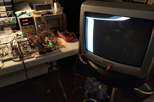
Hooked up to a television (resistor values 1000Ohm on pin 0 and 470Ohm on pin 1) and I'm seeing an image for the first time!
Problems: top of the screen is sheared and gray-coloured bar looks black.
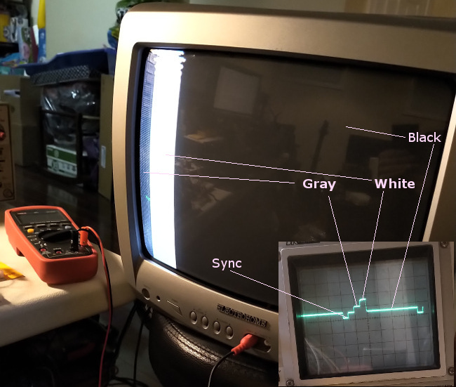
Removed the CMOS inverter and used the TTL outputs of the 74LS244 buffer directly. This made the gray bar visible!
At this point, something is not synchronizing properly, and I believe it's the vertical.
I don't think it's the horizontal because the lines that are NOT sheared are output by the exact same loop and look fine.
Reduced the vertical blanking line count from 20 to 10. Sheared region is smaller.
Reduced the vertical blanking line count from 10 to 5. Sheared region is smaller.
day 6
Reduced the vertical blanking line count from 5 to 2. Sheared region is smaller.
For displaying vertical bars, I found that using OUTI and re-initializing HL to point to the start of a colour array is the fastest.
The image is static and stable. The program which generates it is called NTSC4.
day 7
Started work on a program that updates something on the screen when an input device changes state.
day 8
Finished NTSC5, the program which moves a vertical line on screen whenever a button is pressed.
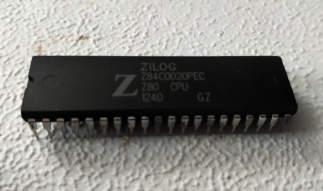
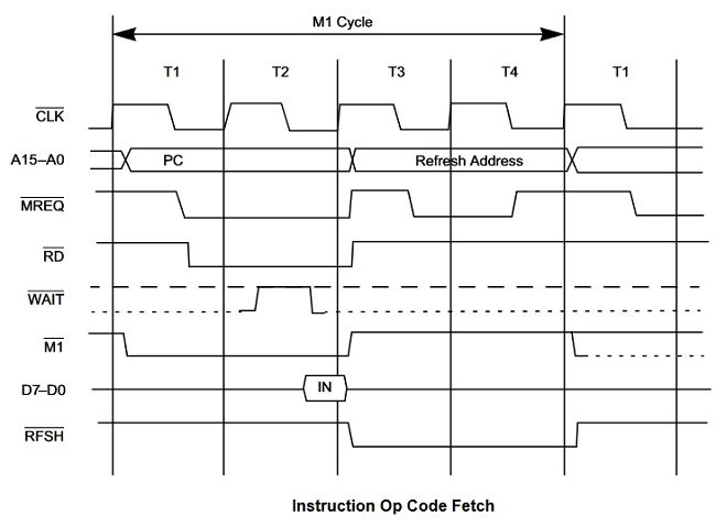
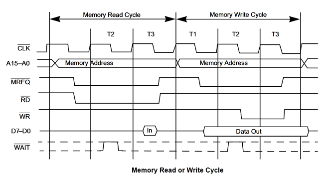
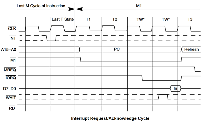
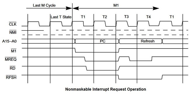
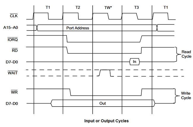
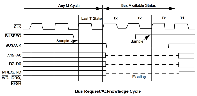
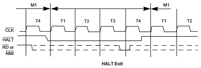
Z80 diagrams
Here are some useful diagrams, including the Z80 pinout, timing diagrams, etc.
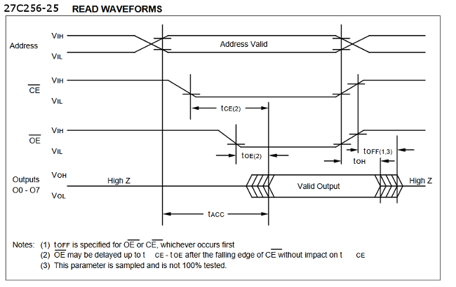
27C256 EPROM diagrams
Here are some useful diagrams, including pinout, timing, etc.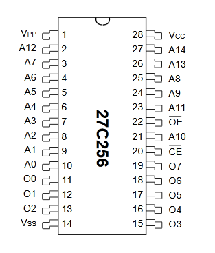
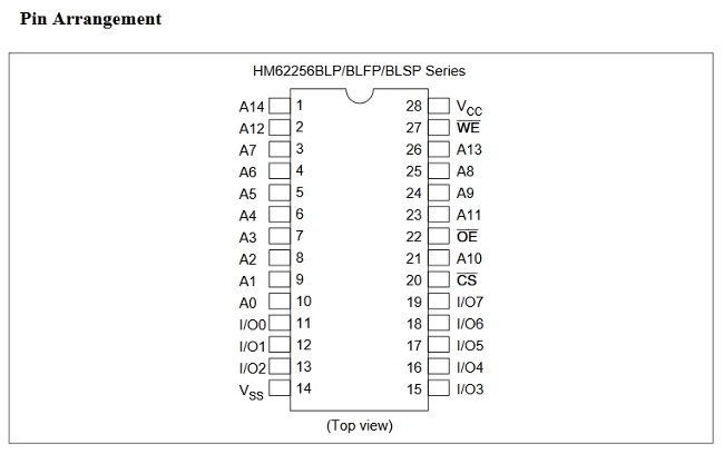
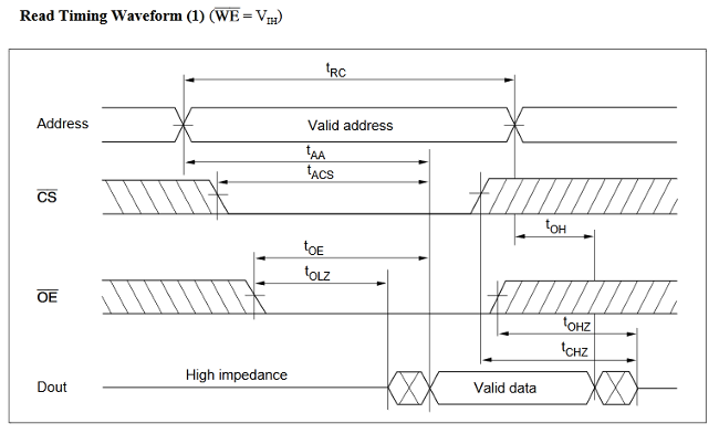
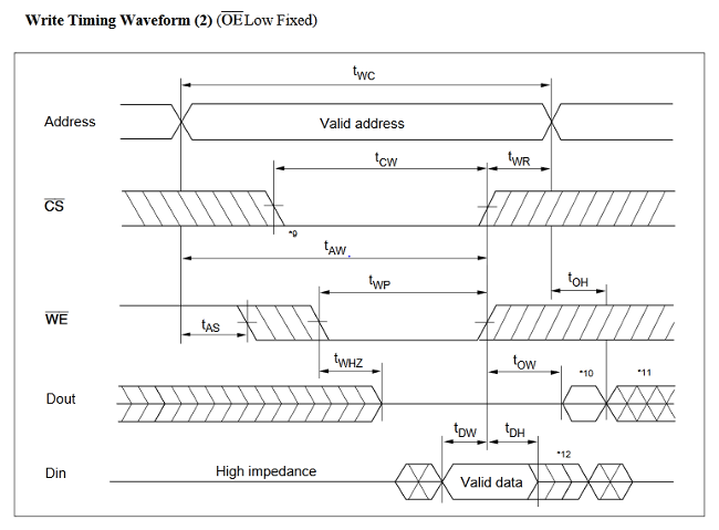
62256 RAM diagrams
Here are some useful diagrams, including pinout, timing, etc.